This article is about an analogue synthesiser.
Figure 1: Analogue Synthesiser Amplitude Controls.
Figure 2: Analogue Synthesiser Frequency Controls.
When I was a student at university our engineering faculty dumped hundreds of 100k logarithmic potentiometers. To prevent those potentiometers from going to waste I decided to use them for frequency control in analogue synthesiser.
Step 1: Design the Circuit
I designed the circuit with six transistor flip-flop oscillators. Three are shown in the diagram below:
Figure 3: Circuit Design.
Step 2: Simulations
Simulations show how the circuit will work.
Figure 4: PSpice Simulations.
Step 3: Make the Circuit
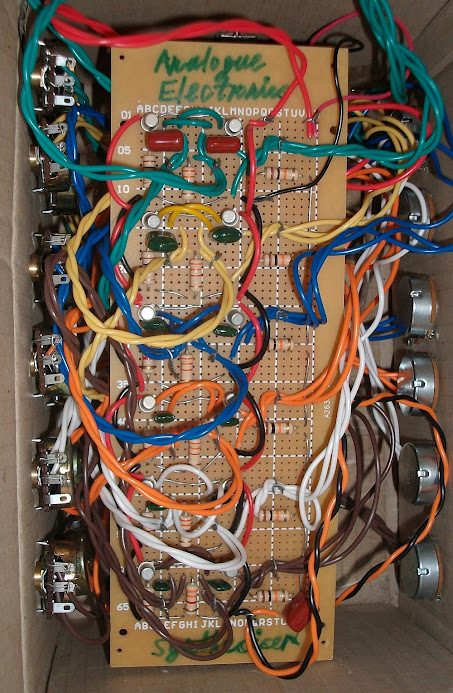
I did not use a soldering iron I twisted the component legs and the wires.
Figure 5: Make the Circuit.
Step 4: Encasement
I used scissors to make holes in the cardboard box for the potentiometers, ON switch and earphone plug.
Figure 6: Put in the Cardboard Box.
Step 5: Testing
I used Hantek 6022BE USB oscilloscope to test the synthesiser.
Figure 7: USB Oscilloscope Plot.
I connected the synthesiser to a Class A transistor power amplifier.
Video of the synthesiser working:
Conclusion
Other alternative design solutions exist. The volume control potentiometers (Rc1b, Rc2b and Rc3b) can be 10 kohms and the mixing resistors (R1, R2 and R3) can be 1 kohms.


Comments
Post a Comment